3D Printing and Ecology: Utilizing Additive Manufacturing to Save a Federally-threatened Native Plant Species


The Evil Weevil

By Harsimran Kalsi

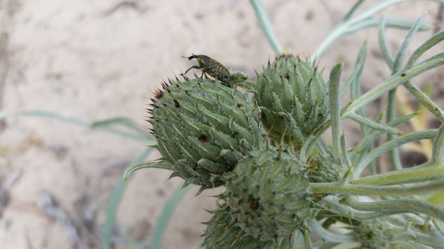
     Previously, I collaborated with Prof. Alyssa Hakes of the Biology department on a very interesting project, which highlights 3D printing’s high versatility and interdisciplinary potential. We worked on a project which may allow us to protect an endangered plant species known as the Pitcher’s Thistle (Cirsium pitcheri). This unique intersection of ecology and 3D printing is not intuitive at first, but it’s also an intersection that has only recently been explored by the scientific community.

     Prof. Hakes has a wonderful page on experiments.com (https://experiment.com/projects/can-we-trap-invasive-weevils-and-protect-the-federally-threatened-pitcher-s-thistle) which describes the project in depth. In short summary, the goal was to fabricate decoys of the Pitcher’s Thistle (PT) to attract weevils away from the real and vulnerable plant. We wanted to make the decoys as high fidelity as possible considering things like shape, size, color, and reflectiveness. We also wanted to optimize these decoys such that they were easy to print/work with and easy to deploy in the field.

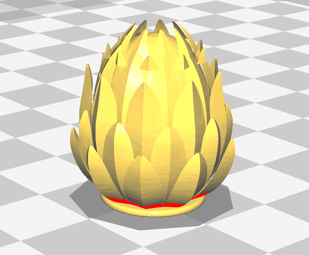
     During the initial design phase, one of the biggest challenges was trying to replicate the topology of the PT. The small pineapple-like protrusions on the curved surface of the bud, proved difficult to design and we anticipated that it might also be challenging to print. In a stroke of genius, Angela Vanden Elzen had the creative idea to modify a design she’d happened to come across on Thingiverse. The file was of a lamp shade which Angela then further modified by placing two inside one another, adding a sphere to the middle, and inserting a hole through the base (so the decoy could be placed onto a dowel which would act as the plant stem). This ultimately resulted in a decoy which looked something like this:

A snapshot of the decoy design Angela made

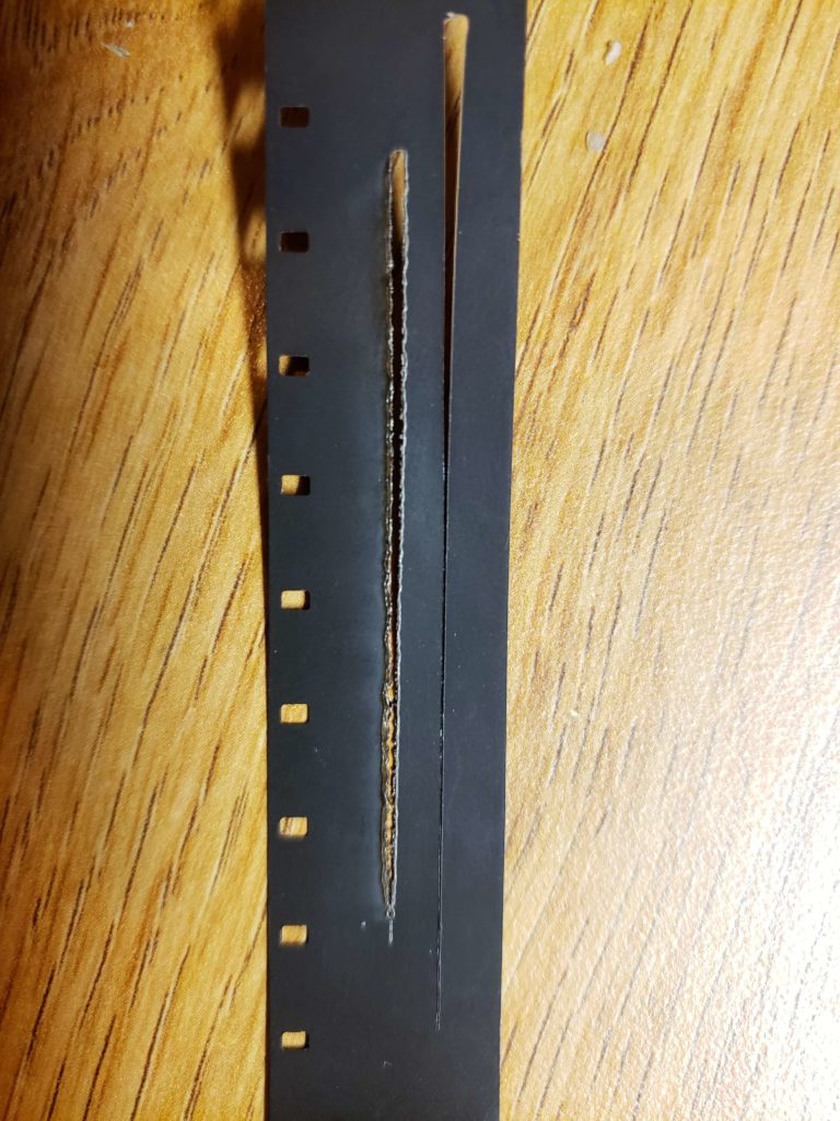
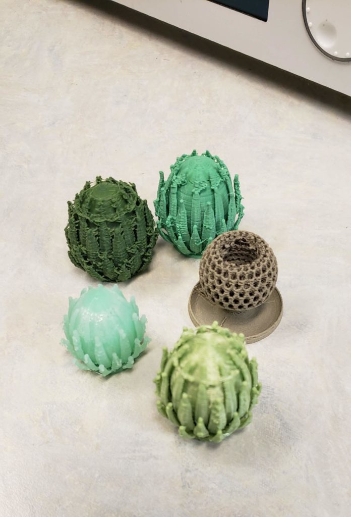
     Interestingly, we discovered that the “spiky” parts of this design weren’t printed exactly like they are shown in the .stl file. Instead, because of printing limitations (e.g. the angles of these edges) we ended up with decoys that displayed intricate, thin, somewhat “frilly”, and lengthwise fibers which surrounded the bud. Ultimately, these fibers actually helped make the decoys even more realistic in terms of texture. They also facilitated some of our feasibility constraints (e.g. no supports in the design makes it quick to scale up printing and the protrusions may make adding/maintaining adhesive easier).

     As we were printing, we utilized several different shades of green (including an algal based filament which was surprisingly . . . aromatic). We initially relied on prof. Hakes’ previous field experience to determine colors that best match the PT. Later we decided we could use images of the PT (taken by prof. Hakes in the field) to obtain a hex code and subsequently a customized color filament. But where could we order customized color filament? As it turns out, about 10 minutes away from the Makerspace is a local business called Coex, which supplies several different types of filament. We then began collaborating with them to create this custom filament.

A few prototypes printed with different filaments.

            Finally, we began printing the fourth (or so) iteration of the decay using the custom filament from Coex. We batch printed several for prof. Hakes to use for field experiments over the summer. For more updates about the project, check out this link: https://experiment.com/projects/can-we-trap-invasive-weevils-and-protect-the-federally-threatened-pitcher-s-thistle/labnotes?tag=project-milestone#labnotes

Acknowledgements:
Special thanks to Dr. Alyssa Hakes and Angela Vanden Elzen for their support and guidance throughout this project.

Update: The Lawrence University news blog wrote a story about this project at https://www.lawrence.edu/articles/research-looks-invasive-weevils-along-lake-michigan-shoreline

Making sound with film

By Kelvin Maestre

Laser cut film

This winter, I took a course in Artisanal Animation. For my final, I was tasked with making an animation using any of the mediums we had studied. I was personally drawn to direct on film animation. It wasn’t the images that I was after, but the sound. The biggest inspiration for the project was Norman McLaren. McLaren was an animator for the national film board of Canada. He specialized in direct on film animation. One of his most impressive feats in the medium was being able to create his own hand drawn sound. I had made previous attempts to emulate McLaren’s process with little success. This time around, I decided I wanted to tackle the project in my own way. My initial thought was to use the laser cutter in the Makerspace, but the test ended in nothing but burnt film.

I had to consider another option. The only other machine I could use was the silhouette cameo. I was hesitant at first because I had never extensively used the machine. To my surprise, it was very easy to use making my overall process faster. Now I had the tools to etch the film, now it was time for the sound.

Sadly you can not just plop and audio file in the Silhouette cameo’s software. The cameo works best with vector based graphics, so get our sound to be cut-able we need to make it into an image file first. A quick Google search for “Sound to waveform graphic” yielded a website that does just that (link will be below). Once I had a image of my sound file, I ported it into the cameo’s software, resized the audio image, lined it up, and hit send.

One of the images from my stop motion animation

I wanted to see how far I could push the technology, and so I tried to etch a stop motion animation I made of my hand. The animation was shot in black in white (easier for the software to recognize), each image was then combined into rows of 24, plopped into the cameo software, and cut. The results was imagery that didn’t reflect the source it came from. The machine had added a layer of abstraction (you can see the result at the end!)

Here is a link to a video of the film being run through a projector!

Below is a list of links I used to do this project, including a link to an in-depth guide on how to do this yourself:

Makerspace in the News

Our awesome Communications department has been putting together some great content about the makerspace!

Video: This is Lawrence- Makerspace

Blog Post: 2 Minutes With… Kelvin Maestre

Kelvin Maestre ’21, watches as a laser cutter starts its work on a piece of wood in the Makerspace on the first floor of the Seeley G. Mudd Library. (Photo by Danny Damiani)

Thanks to our Communications friends for helping us spread the news about the Lawrence University Makerspace!

Three Approaches to Making Self-Driving RC Cars

By Wenchao Liu

There are numerous technologies used in a real self-driving car. However, when it comes to self-driving RC cars, people normally just use a subset of those technologies. The different technologies use different sensors and different algorithms. Here, I will go through three popular ones.

The simplest approach involves no sensors whatsoever. How is that possible? Well, it’s possible if you can just manually drive through the course once, record the steering and throttle inputs, and replay them at the same starting point. The drawback of this approach is that the car drifts, meaning the car deviates further from the original trajectory as it goes further. That said, this simple approach can tackle all the autonomous RC car challenges as long as they satisfy a few conditions. First, you have to have access to the course before the race. Second, the course does not change. Finally, you can place the car exactly where you originally put it when you recorded the data. It also helps if the rule only allows one car per race, so no other cars would pump into yours.

The second approach involves a camera and a neural network. The flagship product of this approach is the Donkey Car, which uses only one camera and one Raspberry Pi. You first have to drive through the course a couple times to collect training data for the neural network. Because of the computation constrains of the Pi, you have to upload the data to another more powerful computer, train the neural network there and transfer the trained model to the Pi. I have no personal experience with this approach, because cameras, computer vision and neural networks are too much for me! That said, I know for a fact that this approach doesn’t work in total darkness and might not work well if lighting changes a lot.

The third approach is Lidar-based, and it is my favorite. The pipeline is to use SLAM, collect waypoints by manually driving through the course, and use motion planning and trajectory tracking. SLAM refers to simultaneous localization and mapping, which means the car localizes itself and maps the environment at the same time. After the car has a map and knows where it is, you can manually drive the car and collect waypoints. Once you have the waypoints the car should hit, you use motion planning to plan for the trajectory through the waypoints and trajectory tracking to make the car follow the desired trajectory. This approach is the most powerful, because it can tackle dynamic environments. For instance, if a car stopped in front of you, your motion planning algorithm will give you another path to go around the car.

Here you have it, three approaches for making an RC car drive autonomously in a course. Real self-driving cars are definitely more sophisticated, but some ideas are very similar. For instance, Tesla’s approach is using mostly cameras and no Lidars. Other companies such as Waymo and GM Cruise use both cameras and Lidars. Only time will tell which one will prevail!